Liquid Crystal Display (LCD)
Introduction
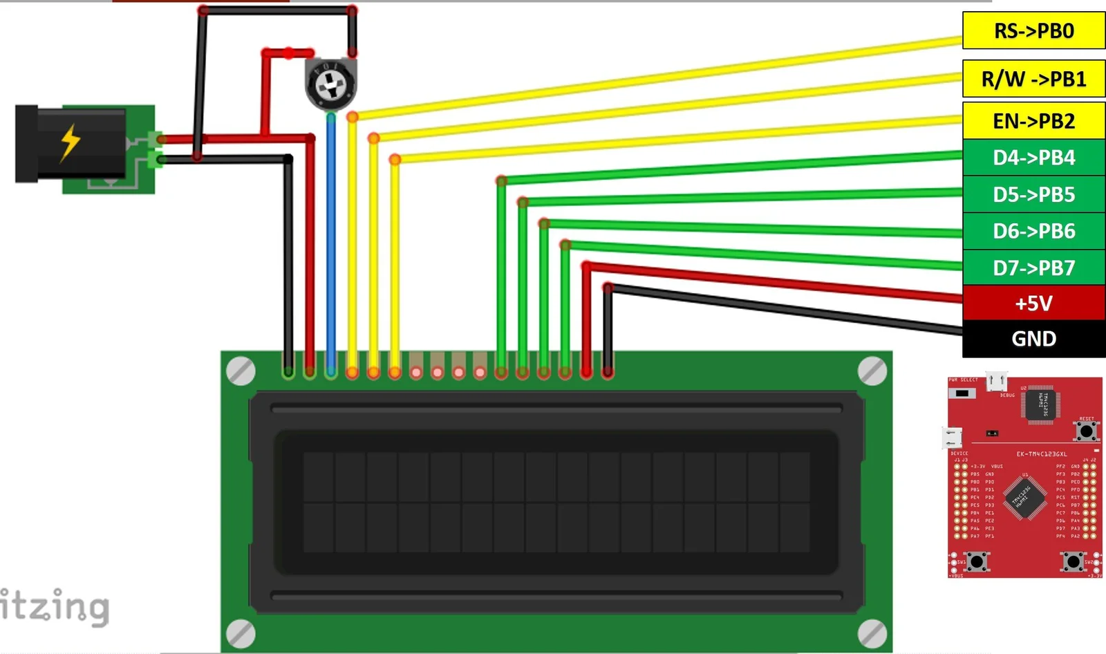
The 16x2 LCD module (HD44780 controller) is commonly used in embedded systems to display text. It shows 16 characters per line on 2 lines. This guide explains how to interface it with the TM4C123 microcontroller using the efficient 4-bit mode.
LCD Basics
Registers:
- Command Register: Sends instructions (e.g., clear display).
- Data Register: Sends characters to display.
Control Pins:
- RS: Selects command or data register.
- RW: Selects read or write mode.
- E: Enables data latch.
Data Pins:
- D0-D7: Used to send data; in 4-bit mode only D4-D7 are used.
Important
Data is sent in two parts: first the upper 4 bits, then the lower 4 bits.Each 8-bit. value requires two writes, toggling the E pin after each to latch the data.
Initialization Steps (4-bit Mode)
Set RS, RW, E to low and wait 40 ms after power-on.
Send command
0x30(upper nibble only) three times with delays (>4.1 ms, >100 μs, >100 μs).Send
0x20(upper nibble only) to switch to 4-bit mode.Send full commands:
0x28: 4-bit mode, 2 lines, 5x7 dots0x0C: Display on, cursor off, blink off0x06: Increment cursor, no display shift0x01: Clear display0x02: Return home
Note
Steps 2-3 send only the upper nibble since LCD isn’t in 4-bit mode yet. After step 3, send full 8-bit commands in two nibbles.
LCD Commands
| Command | Hex Range | Description & Details |
|---|---|---|
| Clear Display | 0x01 | Clears screen, sets cursor to home (address 0). |
| Return Home | 0x02 | Cursor returns to home (address 0). |
| Entry Mode Set | 0x04–0x07 | Controls cursor move direction & display shift: |
- 0x04: cursor moves left, no shift | ||
- 0x06: cursor moves right, no shift (default) | ||
| - Others enable display shift while moving cursor | ||
| Display Control | 0x08–0x0F | Turns display, cursor, and blink on/off: |
- 0x08: display off | ||
- 0x0C: display on, cursor off | ||
- 0x0E: display and cursor on | ||
- 0x0F: display, cursor, and blink on | ||
| Cursor/Display Shift | 0x10–0x1F | Shifts cursor or display left or right. |
0x18 | Shift display left | |
0x1C | Shift display right | |
| Set DDRAM Address | 0x80 + addr | Moves cursor to DDRAM address (e.g., 0x80 start of 1st line, 0xC0 start of 2nd line). |
| Function Set | 0x20–0x3F | Sets interface parameters (bit flags): |
| - Bit 4: Data length (0=4-bit, 1=8-bit) | ||
| - Bit 3: Number of lines (0=1 line, 1=2 lines) | ||
| - Bit 2: Font type (0=5x8 dots, 1=5x10 dots) | ||
Example: 0x28 = 4-bit, 2 lines, 5x8 font |
Example Code
#include "TM4C123.h"
#include "lcd.h"


int main(void)
{

    LCD_Init();
    LCD_Clear();        // Ensure display is clear
    LCD_SetCursor(0,0); // Set cursor to beginning
	LCD_Print("ENCS4110 Lab");

    while(1)
    {
    }
}#include "lcd.h"
#define SYSTEM_CLOCK_HZ 50000000 // 50 MHz system clock
#define CYCLES_PER_US (SYSTEM_CLOCK_HZ / 1000000)
//====================[ SysTick Delay Functions ]====================
void SysTick_Init(void)
{
SysTick->CTRL = 0;
SysTick->LOAD = CYCLES_PER_US - 1; // 1us delay at 50MHz
SysTick->VAL = 0;
SysTick->CTRL = 0x5; // Enable with system clock
}
void delay_us(int us)
{
SysTick->LOAD = (CYCLES_PER_US * us) - 1;
SysTick->VAL = 0;
SysTick->CTRL = 0x5; // Enable with system clock
while ((SysTick->CTRL & 0x10000) == 0);
SysTick->CTRL = 0;
}
void delay_ms(int ms)
{
while (ms--)
delay_us(1000);
}
//====================[ LCD Helper Functions ]====================
void LCD_EnablePulse(void)
{
delay_us(1);
GPIOB->DATA |= EN;
delay_us(1);
GPIOB->DATA &= ~EN;
delay_us(1);
}
void LCD_SendNibble(unsigned char nibble)
{
// Send nibble to PB4–PB7
GPIOB->DATA = (GPIOB->DATA & ~DATA_MASK) | ((nibble << 4) & DATA_MASK);
LCD_EnablePulse();
}
//====================[ LCD Initialization ]====================
void LCD_Init(void)
{
// Enable clock to PORTB
SYSCTL->RCGCGPIO |= (1 << 1);
while ((SYSCTL->PRGPIO & (1 << 1)) == 0)
;
// Configure PB0 (RS), PB1 (EN), PB4–PB7 (data) as output
GPIOB->DIR |= RS | EN | DATA_MASK;
GPIOB->DEN |= RS | EN | DATA_MASK;
GPIOB->DATA &= ~(RS | EN | DATA_MASK); // Clear all
SysTick_Init();
delay_ms(50); // Wait for LCD to power up
// Initialization sequence (8-bit interface mode to start)
LCD_SendNibble(0x03);
delay_ms(5);
LCD_SendNibble(0x03);
delay_us(150);
LCD_SendNibble(0x03);
delay_us(150);
LCD_SendNibble(0x02); // Set 4-bit mode
delay_us(150);
// Now in 4-bit mode: use full commands
LCD_Command(0x28); // Function set: 4-bit, 2 lines, 5x8 dots
LCD_Command(0x0C); // Display ON, Cursor OFF
LCD_Command(0x06); // Entry mode: increment cursor
LCD_Command(0x01); // Clear display
delay_ms(2);
}
//====================[ LCD Command/Data API ]====================
void LCD_Command(unsigned char command)
{
GPIOB->DATA &= ~RS; // RS = 0 for command
delay_us(1);
LCD_SendNibble(command >> 4); // Upper nibble
LCD_SendNibble(command & 0x0F); // Lower nibble
delay_ms(2);
}
void LCD_Data(unsigned char data)
{
GPIOB->DATA |= RS; // RS = 1 for data
delay_us(1);
LCD_SendNibble(data >> 4);
LCD_SendNibble(data & 0x0F);
delay_ms(1);
}
void LCD_Clear(void)
{
LCD_Command(0x01);
delay_ms(2);
}
void LCD_SetCursor(unsigned char row, unsigned char col)
{
unsigned char address = (row == 0) ? 0x80 + col : 0xC0 + col;
LCD_Command(address);
delay_ms(1);
}
void LCD_Print(char *str)
{
while (*str)
{
LCD_Data(*str++);
}
}#ifndef LCD_H
#define LCD_H
#include "TM4C123.h"
// LCD pin definitions (connected to PORTB)
#define RS (1 << 0) // PB0
#define EN (1 << 2) // PB2
#define DATA_MASK 0xF0 // PB4–PB7
// Function prototypes
void LCD_Init(void);
void LCD_Command(unsigned char cmd);
void LCD_Data(unsigned char data);
void LCD_Clear(void);
void LCD_SetCursor(unsigned char row, unsigned char col);
void LCD_Print(char *str);
void delay_us(int us);
void delay_ms(int ms);
#endifLab Work
Modify the code
Update the existing program to display your
nameon the first line and yourIDon the second line of the LCD.Name scrolling with button control
Write a program that:
- Displays your
nameon the LCD. - Allows the name to scroll
leftorright. - Uses the two on-board push buttons (with interrupts) to control the scrolling direction.
- Displays your
Bidirectional shifting after button press
Write a program that:
- Displays your
nameon the first row and yourIDon the second row. - The name (first row) continuously shifts
right. - The ID (second row) continuously shifts
left. - The shifting starts only after a button press by the user.
- Displays your