Universal Asynchronous Receiver-Transmitter (UART)
Introduction
UART (Universal Asynchronous Receiver-Transmitter) is a serial communication protocol used to transmit and receive data between devices. It is widely used in embedded systems due to its simplicity and asynchronous nature, meaning no shared clock is needed between communicating devices. This makes UART highly versatile for microcontroller communication with external devices like PCs, sensors, or other microcontrollers.
In this document, we will explore UART communication using the TM4C123G microcontroller. We will cover UART concepts, configuration, and practical implementation using C. The objective is to gain a clear understanding of UART and how to program it efficiently on the TM4C123G.
Key Topics
- UART Communication Basics
- UART Configuration on TM4C123G
- Implementing UART Initialization in C
- Sending and Receiving Data
- Understanding UART Registers
UART Basics
UART allows full-duplex communication, meaning it can send and receive data simultaneously. Key elements of UART communication include:
- Baud Rate: The speed of data transmission measured in bits per second (bps). Examples: 9600, 115200.
- Data Format: Composed of data bits (usually 8), parity bit (optional), and stop bits (usually 1 or 2).
- Start Bit: Marks the beginning of a data frame.
- Data Bits: Typically 8 bits that hold the actual data.
- Parity Bit: Optional bit used for error detection.
- Stop Bit: Marks the end of the data frame.
UART Configuration
Step 1: Enabling Clocks
To use UART0 and GPIOA, enable the respective clocks:
SYSCTL->RCGCUART |= (1 << 0);  // Enable UART0 clock
SYSCTL->RCGCGPIO |= (1 << 0);  // Enable GPIOA clock
Step 2: Configuring GPIO Pins
UART0 uses PA0 (RX) and PA1 (TX). Configure these pins for UART functionality:
GPIOA->AFSEL |= (1 << 0) | (1 << 1);  // Alternate function
GPIOA->PCTL |= (1 << 0) | (1 << 4);    // UART function
GPIOA->DEN |= (1 << 0) | (1 << 1);      // Digital enable
Step 3: Disabling UART0
Disabling the UART during configuration helps prevent unwanted transmissions:
UART0->CTL = 0; // Disable UART0Step 4: Setting the Baud Rate
The baud rate divisor is calculated as:
Baud Rate Divisor = System Clock / (16 × Baud Rate)
IBRD = Integer part
FBRD = Fractional part × 64 + 0.5
For a 50 MHz system clock and 115200 baud rate:
Baud Rate Divisor = 50,000,000 / (16 × 115200) ≈ 27.126
IBRD = 27
FBRD = (0.126 × 64) + 0.5 ≈ 8
Code:
UART0->IBRD = 27;
UART0->FBRD = 8;
Step 5: Configuring Line Control
Configure for 8 data bits, no parity, and 1 stop bit:
UART0->LCRH = (0x3 << 5); // 8-bit, no parity, 1 stop bitStep 6: Clock Source Selection
UART0->CC = 0; // Use the system clockStep 7: Enabling UART0
Enable UART and configure it for both transmission and reception:
UART0->CTL = (1 << 0) | (1 << 8) | (1 << 9); // Enable UART, TX, RXStep 8: Sending and Receiving Data
Sending Data
void UART0_WriteChar(char c) {
    while ((UART0->FR & (1 << 5)) != 0);  // Wait for space
    UART0->DR = c;  // Transmit character
}
Receiving Data
char UART0_ReadChar() {
    while ((UART0->FR & (1 << 4)) != 0);  // Wait for data
    return (char)(UART0->DR & 0xFF);      // Read received data
}
UART Registers
FR Register
The FR (Flag Register) indicates the status of the UART. It contains flags for various conditions:
| Bit | Name | Description |
|---|---|---|
| 0 | CTS | Clear to send (not used) |
| 3 | BUSY | Transmitter busy |
| 4 | RXFE | Receive FIFO empty |
| 5 | TXFF | Transmit FIFO full |
| 6 | RXFF | Receive FIFO full |
| 7 | TXFE | Transmit FIFO empty |
DR Register
The DR register holds the transmitted or received data. The lower 8 bits (0-7) contain the data, while the upper bits are used for error flags.
Example Code
#include <stdio.h>
#include "TM4C123.h"
#include "uart.h"

int main(void) {
    UART0_Init();
    UART0_WriteString("Hello World!\r\n");  // Send greeting with newline

    while (1) {
		char buff[16];
		UART0_ReadString(buff, 16);

		UART0_WriteString("Recived: ");
		UART0_WriteString(buff);
		UART0_WriteString("\r\n");
    }
}#include "uart.h"
#define MAX_STR_LEN 50
// Function to send a single character via UART0
void UART0_WriteChar(char c) {
// Wait until the transmit FIFO is not full
// UART0->FR bit 5 (TXFF) = 1 means FIFO is full, so wait until it becomes 0
while ((UART0->FR & (1 << 5)) != 0);
// Write the character to the Data Register to transmit
UART0->DR = c;
}
// Function to send a null-terminated string via UART0
void UART0_WriteString(char *str) {
// Loop through each character until null terminator
while (*str) {
// Send each character using UART0_WriteChar
UART0_WriteChar(*(str++));
}
}
// UART0 initialization function
void UART0_Init() {
// Enable clock to UART0 module (bit 0)
SYSCTL->RCGCUART |= (1 << 0);
// Enable clock to GPIO Port A (bit 0)
SYSCTL->RCGCGPIO |= (1 << 0);
// Enable alternate function on PA0 (RX) and PA1 (TX)
GPIOA->AFSEL |= U0_RX | U0_TX;
// Configure PA0 and PA1 pins for UART function in Port Control Register
// U0_RX corresponds to PA0 (bits 3:0) and U0_TX corresponds to PA1 (bits 7:4)
GPIOA->PCTL |= (1 << 0) | (1 << 4);
// Enable digital function for PA0 and PA1 pins
GPIOA->DEN |= U0_RX | U0_TX;
// Disable UART0 while configuring
UART0->CTL = 0;
// Set integer baud rate divisor for 115200 baud with 50MHz clock
UART0->IBRD = 27;
// Set fractional baud rate divisor
UART0->FBRD = 8;
// Configure Line Control for 8 data bits, no parity, one stop bit, and FIFOs enabled
// 0x60 = 0b01100000: bit 6 (FEN) = 1 enable FIFO, bits 5-6 (WLEN) = 11 for 8 bits
UART0->LCRH = 0x60;
// Use system clock for UART
UART0->CC = 0;
// Enable UART0, TX and RX
// Bit 0 = UARTEN, bit 8 = TXE, bit 9 = RXE
UART0->CTL = (1 << 0) | (1 << 8) | (1 << 9);
}
char UART0_ReadChar(void) {
while (UART0->FR & (1 << 4)); // Wait while RX FIFO empty
return (char)(UART0->DR & 0xFF);
}
void UART0_ReadString(char *buffer, int maxLen) {
int i = 0;
char c;
while (i < (maxLen - 1)) { // Leave space for null terminator
c = UART0_ReadChar();
// Echo character back (optional)
UART0_WriteChar(c);
if (c == '\r' || c == '\n') { // End of input
UART0_WriteString("\r\n");
break;
}
buffer[i++] = c;
}
buffer[i] = '\0'; // Null terminate the string
}#ifndef UART_H
#define UART_H
#include "TM4C123.h" // Or your MCU's main header
#define U0_TX 2
#define U0_RX 1
void UART0_WriteChar(char c);
void UART0_WriteString(char *str);
char UART0_ReadChar();
void UART0_ReadString(char *buffer, int maxLen);
void UART0_Init();
#endif // UART_HThe above code demonstrates a simple UART communication setup. The UART0_Init function initializes the UART0 module, while UART0_WriteChar and UART0_ReadChar functions handle data transmission and reception, respectively. To be able to communicate with the microcontroller, you can use a terminal program on your PC PuTTY to send and receive data over the serial port. Make sure to set the baud rate and other parameters to match the configuration in your code. The following image shows how to set up the serial connection in PuTTY:
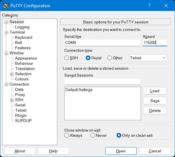
You should replace the COM port with the one assigned to your TM4C123G LaunchPad. You can find this in the Device Manager under Ports (COM & LPT). The baud rate should match the one set in your code (e.g., 115200).